Adaptive Monte Carlo localization. More...
Adaptive Monte Carlo localization.
The amcl driver implements the Adaptive Monte-Carlo Localization algorithm described by Dieter Fox.
At the conceptual level, the amcl driver maintains a probability distribution over the set of all possible robot poses, and updates this distribution using data from odometry, sonar and/or laser range-finders. The driver also requires a pre-defined map of the environment against which to compare observed sensor values.
At the implementation level, the amcl driver represents the probability distribution using a particle filter. The filter is "adaptive" because it dynamically adjusts the number of particles in the filter: when the robot's pose is highly uncertain, the number of particles is increased; when the robot's pose is well determined, the number of particles is decreased. The driver is therefore able make a trade-off between processing speed and localization accuracy.
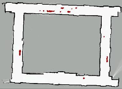
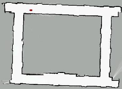
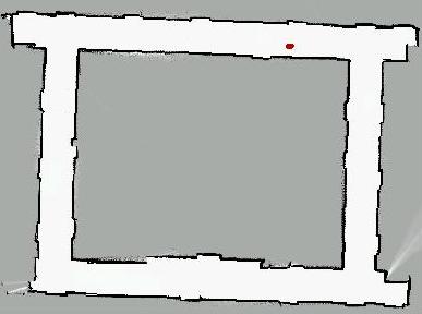
As an example, consider the sequence of images shown below. This sequence shows the filter converging from an initial configuration in which the pose of the robot is entirely unknown to a final configuration in which the pose of the robot is well determined. At the same time, the number of particles in the filter decreases from 100,000 to less than 100. Convergence in this case is relatively slow.


The amcl driver has the the usual features – and failures – associated with simple Monte-Carlo Localization techniques:
- If the robot's initial pose is specified as being completely unknown, the driver's estimate will usually converge to correct pose. This assumes that the particle filter starts with a large number of particles (to cover the space of possible poses), and that the robot is driven some distance through the environment (to collect observations).
- If the robot's initial pose is specified accurately, but incorrectly, or if the robot becomes lost (e.g., by picking it up and replacing it elsewhere) the driver's estimate will not converge on the correct pose. Such situations require the use of more advanced techniques that have not yet been implemented.
The amcl driver also has some slightly unusual temporal behavior:
- When the number of particles in the filter is large, data may arrive from the sensors faster than it can be processed. When this happens, data is queued up for later processing, but the driver continues to generate an up-to-date estimate for the robot pose. Thus, for example, at time t = 10 sec, the driver may have only processed sensor readings up until time t = 5 sec, but will nevertheless generate an estimate (prediction) of where the robot is at t = 10 sec. The adaptive nature of the algorithm more-or-less guarantees that the driver will eventual "catch up": as more sensor readings are processed, the number of particles will generally decrease, and the sensor update step of the algorithm will run faster.
- Caveats
At the time of writing, this driver is still evolving. The sensor models, in particular, are currently over-simplified and under-parameterized (there are lots of magic numbers lurking about the place). Consequently, while this driver is known to work for certain hardware configurations (think Pioneer2DX with a SICKLMS200 laser range-finder), other configurations may require some refinement of the sensor models.
- Provides
- localize : this interface provides a (sort of) representative sample of the current pose hypotheses, weighted by likelihood.
- position2d : this interface provides just the most-likely hypothesis, formatted as position data, which you can (at your peril) pretend came from a perfect odometry system
- Requires
The amcl driver requires the following interfaces, some of them named:
- "odometry" position2d : source of odometry information
- laser : source of laser scans
- "laser" map : a map in which to localize the robot, by fusing odometry and laser/sonar data.
- In principle supported, but currently disabled are:
- fiducial
- "imu" position2d
- sonar
- gps
- wifi
- Configuration requests
- PLAYER_LOCALIZE_REQ_SET_POSE
- PLAYER_LOCALIZE_REQ_GET_PARTICLES
- PLAYER_POSITION2D_REQ_GET_GEOM
- Configuration file options
- Particle filter settings:
- odom_init (integer)
- Default: 1
- Use the odometry device as the "action" sensor
- pf_min_samples (integer)
- Default: 100
- Lower bound on the number of samples to maintain in the particle filter.
- pf_max_samples (integer)
- Default: 10000
- Upper bound on the number of samples to maintain in the particle filter.
- pf_err (float)
- Default: 0.01
- Control parameter for the particle set size. See notes below.
- pf_z (float)
- Default: 3
- Control parameter for the particle set size. See notes below.
- init_pose (tuple: [length length angle])
- Default: [0 0 0] (m m rad)
- Initial pose estimate (mean value) for the robot.
- init_pose_var (tuple: [length length angle])
- Default: [1 1 2pi] (m m rad)
- Uncertainty in the initial pose estimate.
- update_thresh (tuple: [length angle])
- Default: [0.2 pi/6] (m rad)
- Minimum change required in action sensor to force update in particle filter.
- odom_drift[0-2] (float tuples)
- Default:
- odom_drift[0] [0.2 0.0 0.0]
- odom_drift[1] [0.0 0.2 0.0]
- odom_drift[2] [0.2 0.0 0.2]
- Set the 3 rows of the covariance matrix used for odometric drift.
- Default:
- odom_init (integer)
- Laser settings:
- laser_pose (length tuple)
- Default: [0 0 0]
- Pose of the laser sensor in the robot's coordinate system
- laser_max_beams (integer)
- Default: 6
- Maximum number of range readings being used
- laser_range_max (length)
- Default: 8.192 m
- Maximum range returned by laser
- laser_range_var (length)
- Default: 0.1 m
- Variance in range data returned by laser
- laser_range_bad (float)
- Default 0.1
- ???
- laser_pose (length tuple)
- Debugging:
- enable_gui (integer)
- Default: 0
- Set this to 1 to enable the built-in driver GUI (useful for debugging). Player must also be built with
configure–enable-rtkguifor this option to have any effect.
- enable_gui (integer)
- Notes
- Coordinate System: The origin of the global coordinate system corresponds to the center of occupancy grid map. Standard coordinate orientation is used; i.e., positive x is towards the right of the map, positive y towards the top of the map.
- Number of particles: The number of particles in the filter can be controlled using the configuration file parameters
pf_errandpf_z. Specifically,pf_erris the maximum allowed error between the true distribution and the estimated distribution, whilepf_zis the upper standard normal quantile for (1 - p), where p is the probability that the error on the estimated distribution will be less thanpf_err. If you dont know what that means, dont worry, I'm not exactly sure either. See Fox's paper for a more meaningful explanation. - Speed: Many factors affect the speed at which the
amcldriver runs, but the following tips might be helpful:- Reducing the number of laser range readings being used (
laser_max_beamsin the configuration file) will significantly increase driver speed, but may also lead to slower convergence and/or less accurate localization. - Increasing the allowed error
pf_errand reducing the quantilepf_zwill lead to smaller particle sets and will hence increase driver speed. This may also lead, however, to over-convergence. As a benchmark, this driver has been successfully deployed on a Pioneer2DX equipped with a SICK LMS200 and a 266MHz Mobile Pentium with 32Mb of RAM.
- Reducing the number of laser range readings being used (
- Memory: The two key factors affecting memory usage are:
- The size and resolution of the map.
- The maximum number of particles. As currently configured, the
amcldriver will typically use 10 to 20Mb of memory. On embedded systems, where memory is at a premium, users may have to decrease the map resolution or the maximum number of particles to achieve acceptable preformance.
- Example: Using the amcl driver with a Pioneer robot
The following configuration file illustrates the use of the amcl driver on a Pioneer robot equipped with a SICK LMS200 scanning laser range finder:
driver
(
  name "p2os_position"
  provides ["odometry:::position2d:0"]
  port "/dev/ttyS0"
)
driver
(
  name "sicklms200"
  provides ["laser:0"]
  port "/dev/ttyS2"
)
driver
(
  name "mapfile"
  provides ["map:0"]
  resolution 0.05
  filename "mymap.pgm"
)
driver
(
  name "amcl"
  provides ["localize:0"]
  requires ["odometry:::position2d:0" "laser:0" "laser:::map:0"]
)
Naturally, the port, filename and resolution values should be changed to match your particular configuration.
- Todo:
- Implement / update other sensor models

